
News
Understanding how to identify electronic components on VFD circuit boards is very important. Problems like signal loss can stop machines from working. Issues like too much or too little load can harm circuits. Checking the board step by step keeps signals working well. Testing and finding problems early can make equipment last longer. This also reduces breaks and makes machines work better. Learning these skills protects circuits and improves how things run.
Key Takeaways
Learn about main parts on VFD boards, like resistors, capacitors, and diodes, to know their jobs and fix problems better.
Look closely at the board, check its layout, and inspect solder spots to find problems early and keep machines working well.
Use tools like multimeters and magnifying glasses to check and test parts carefully, helping you find and solve issues correctly.
Common Circuit Board Parts on VFDs
Knowing the main parts of a VFD board helps you find and understand electronic parts better. Below are the most common parts you’ll see:
Resistors
Resistors slow down the flow of electricity. They lower voltage and protect delicate parts. They are small cylinders with colored stripes showing their resistance.
Capacitors
Capacitors hold and release electric energy. They keep voltage steady and signals clear. Look for small cylinders or rectangles with numbers showing their capacity.
Diodes
Diodes let electricity flow in one direction only. They stop damage from reverse voltage. They are tiny cylinders with a stripe showing their direction.
Transistors
Transistors boost or switch electric signals. They help control power in circuits. They usually have three legs and come in different shapes like TO-92 or TO-220.
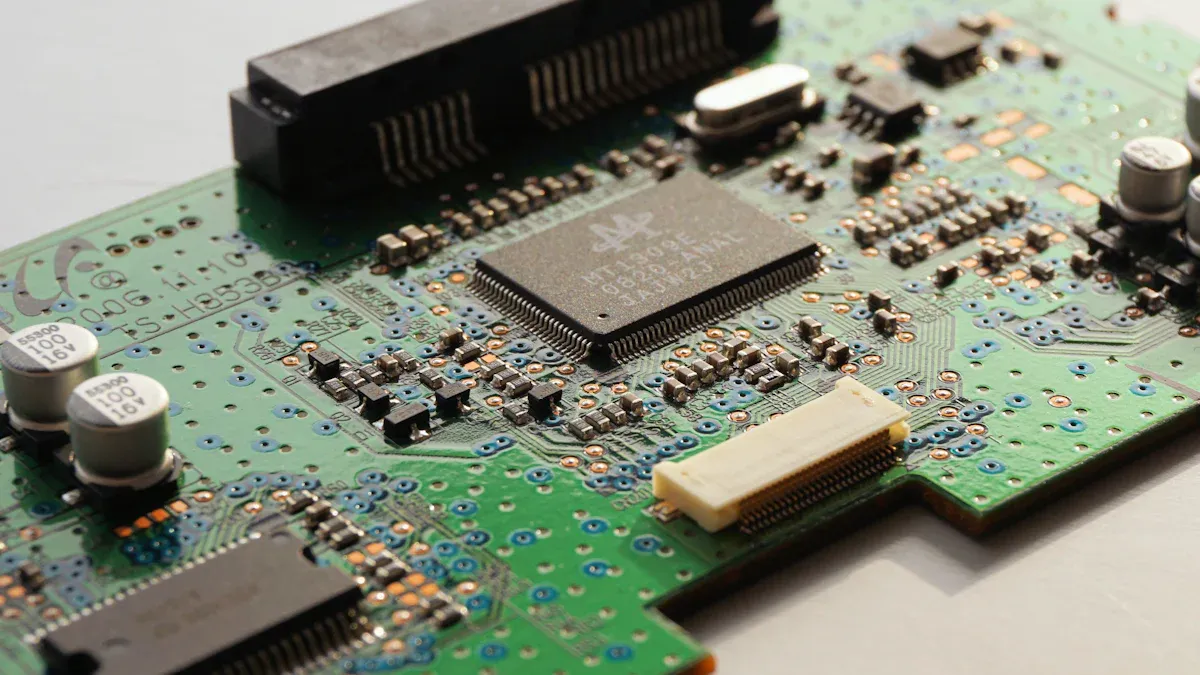
Integrated Circuits (ICs)
ICs are small chips that do many tasks. They combine several parts into one. They look like black rectangles with many pins.
MOSFETs and IGBTs
MOSFETs and IGBTs are special transistors for high power. They handle signal switching in VFDs. They are bigger and often attached to heat sinks to stay cool.
Transformers and Relays
Transformers move energy between circuits, and relays act as switches. Transformers are large with coils, while relays are box-shaped with visible connectors.
Connectors and Terminals
Connectors and terminals join the board to other devices. Common types include:
Barrier blocks for high-power circuits.
Spring blocks for fast, secure links.
Din rail blocks for neat, strong designs.
Through-wall blocks for easy setup and safety.
These parts keep VFDs working properly. Learning to spot them helps you fix and care for boards better.
How to Identify Components on VFD Circuit Boards
Visual Inspection Techniques
Looking at the board carefully helps find and check parts. Follow these steps for a good inspection:
Set up a bright workspace with tools like a magnifying glass.
Clean the board gently to remove dust or dirt.
Study the board layout to see its sections and design.
Use labels and diagrams to find important parts.
Trace power and ground lines, as they are key paths.
Follow signal paths to see how parts connect.
Pay attention to main parts like microcontrollers and regulators.
Check solder joints for cracks or weak spots.
Look for burns, cracks, or discoloration on the board.
Compare the board to its diagram to check for matches.
Write down any problems for fixing later.
This step-by-step method keeps signals working and the board running well.
Using Reference Designators and Circuit Board Labels
Labels and codes make finding parts on the board easier. These printed codes near parts tell you what they are. For example, "R" means resistors, and "C" means capacitors.
Labels also show where parts go and what they do. By using these codes with diagrams, you can quickly find parts and learn their jobs. This is very useful for complex boards.
Tools for Identification
The right tools help you find and test parts easily. Here’s a list of tools and what they do:
Using these tools with careful inspection helps you find and test parts correctly.
How to Read Circuit Boards: Markings and Symbols
Understanding Component Codes and Values
Circuit board parts often have codes and numbers on them. These markings show what the parts do. For example, resistors have colored stripes that tell their resistance. Capacitors have numbers showing how much energy they hold and their voltage. These markings help you quickly find out what each part does.
To understand these codes, use charts or guides. For resistors, a color chart matches the stripes to resistance values. Capacitor numbers follow a format like "104," meaning 100,000 pF. Knowing these codes helps you identify and test parts correctly.
Decoding Manufacturer Markings
Manufacturers put special marks on their parts. These include logos, part numbers, or dates. These marks help you find where the part came from and its details. For example, a transistor with "2N2222" can be searched online for its specs.
Look at these marks when working with circuit boards. They give important details about how the part works. If you see unknown marks, use online tools or catalogs to learn more.
Recognizing Circuit Board Layout Patterns
PCB designs are important for keeping signals clear and circuits working. Here are some common designs and what they do:
Single-Sided Patterns: Simple and cheap, good for basic circuits.
Double-Sided Patterns: Fit more parts, used in amplifiers.
Multilayer Patterns: Handle complex circuits, great for advanced devices.
Power Plane Patterns: Spread power evenly, improve signal quality.
Ground Plane Patterns: Provide stable grounding, reduce noise.
Differential Pair Patterns: Block noise, needed for fast circuits.
Clock Distribution Patterns: Keep timing correct in digital systems.
RF Transmission Line Patterns: Manage high-frequency signals in wireless devices.
By learning these designs, you can read circuit diagrams better. This makes fixing and understanding boards easier.
Advanced Tips for Finding Complex Circuit Board Parts
Spotting Surface-Mount Devices (SMDs)
Surface-Mount Devices (SMDs) are tiny and fit on the board's surface. They are smaller than through-hole parts and save space. SMDs are soldered directly onto the board, making them great for modern circuits. To find SMDs, look at their shapes and markings. For example:
Resistors look like small rectangles with numbers for resistance.
Capacitors may have forked wires or special codes.
Through-hole parts are different because their leads go through the board. These leads are soldered on the other side. SMDs, however, sit flat on the board. The table below shows the differences:
Use a magnifying glass to check SMD markings and connections.
Finding Custom or Special Components
Custom parts often don’t have standard labels, making them tricky to spot. These might include processors or unique chips with brand names or logos. To identify them, look closely for unusual symbols or codes. If you can’t figure them out, use online tools or datasheets for help.
Using Datasheets and Online Tools
Datasheets and online resources are great for learning about parts. First, check the board and write down any markings. Then, search for these markings online or on manufacturer sites. Follow these steps:
Use a magnifying glass to see tiny labels.
Look at datasheets for detailed part info.
Trace how parts connect to understand their jobs.
Ask online forums for advice if needed.
These tools make it easier to understand circuit boards and check parts properly.
Finding parts on VFD boards gets simpler with practice. Begin by carefully looking at the board. Use tools to check circuits and read markings for details. Learn to spot symbols and designs in circuit layouts. Knowing these markings helps you fix circuits better. Keep learning from guides to improve your skills.
FAQ
What tools can you use to find circuit board parts?
Use tools like multimeters, LCR meters, and magnifying glasses. These tools help you see and test parts easily.
How can you spot broken parts on a VFD board?
Check for burns, cracks, or discoloration on the board. Bad solder joints or strange smells may also mean parts are broken.
Can you find parts without using a circuit diagram?
Yes, you can. Use labels, codes, and careful inspection steps. These methods help you find and understand parts without a diagram.
Please give us a message